Dear Harbour,
If You could speak and ask us to name the greatest difficulty of the entire HATS project, our answer would have to be “the tunnels”. Most of the engineering challenges that arose during HATS came from the tunnelling process. This was perhaps inevitable, as we were constructing one of the longest and deepest tunnel systems in the world, and doing so under complex geological conditions.
Our friends in Hong Kong and elsewhere may want to know what those engineering challenges were and how we resolved them. And so, our story continues.

Challenge 1: Water Ingress under High Pressure
Solution: Pre-excavation Grouting System
To understand the tunnelling challenges of the HATS project, it is important to note that Tunnel Boring Machines (TBMs) were used for Stage 1 tunnelling, whereas the drill and blast method was used for Stage 2A tunnelling except a short interconnection tunnel on Stonecutters Island where a TBM was deployed.
In fact, ground water ingress into the tunnels under high pressure had caused significant difficulties from early on during Stage 1 tunnelling works. Water ingress, if not properly controlled, would increase construction difficulties and cause ground water table drawdown leading to ground settlement. We soon learned from Stage 1 experience that pre-excavation grouting was the most effective solution to control water ingress. This method means drilling grout holes around the tunnel perimeter ahead of excavation and injecting grouting material into the holes to seal up rock fissures to reduce the inflow of ground water into the tunnel.
However, it was easier said than done. As the TBMs used in Stage 1 tunnelling works were not equipped with the mechanical drilling equipment required for pre-excavation grouting operation, it was necessary to retrofit them first with such equipment. But the retrofitting works under congested conditions inside the tunnels turned out to be a very challenging task. Stage 1 tunnelling works, though eventually completed safely, gave us hard earned insights to critically examine whether TBMs would be the best choice for HATS Stage 2A tunnel construction.
To find the answer, we consulted leading TBM manufacturers and specialist designers in Europe, but found that the inherent difficulties associated with equipping and operating a TBM with drilling equipment required for pre-excavation grouting still remained unresolved. Concurrently, we studied the drill and blast method in detail, in particular its suitability to tunnelling at great depths, and decided to construct Stage 2A tunnels using the drill and blast method.
The drill and blast method had several major benefits. First, it provided sufficient working space for the pre-excavation grouting system to operate efficiently, which hinged on the use of mechanical drills mounted on a computerised mobile vehicle called a drilling jumbo. Also, with careful application of cutting-edge drill and blast technology, the effects of blasting were well limited, with minimum disturbance to neighbouring communities during Stage 2A tunnelling works. Key logistical issues and statutory constraints, including the delivery of explosives across the Harbour, were well resolved through meticulous planning before Stage 2A works commenced.
Stage 2A tunnelling works also put us at the leading edge of pre-excavation grouting technique making use of micro fine cement and/or a then newly available grouting material called colloidal silica. We were able to achieve for Stage 2A tunnelling a water ingress limit several times more stringent than that of Stage 1 works. This success was well recognised by the industry as a “quantum leap” in pre-excavation grouting technology.
Our efforts in developing and applying the pre-excavation grouting technique also successfully limited settlement in all areas to a negligible level during Stage 2A tunnelling works.

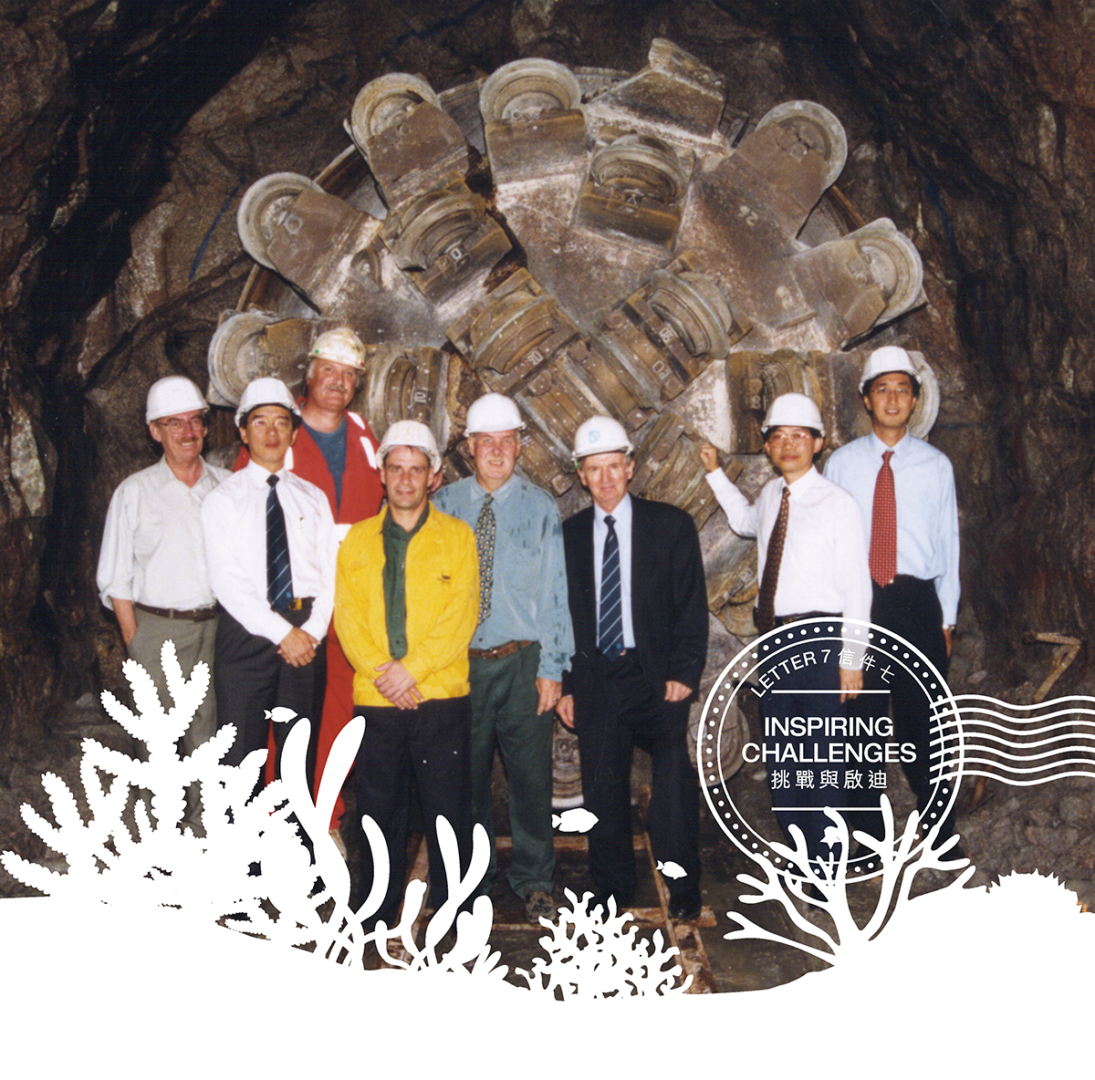
Cutter head of tunnel boring machine
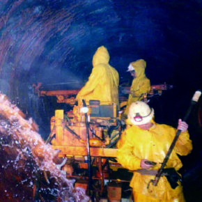
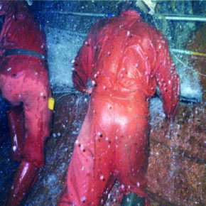
Serious water inflow in Tunnel F from Kwai Chung to Tsing Yi
Challenge 2: Stability Problem in Weak Ground
Solution: Pre-excavation Grouting and Robust Ground Support System
This was related to the water ingress challenge, and again our Stage 1 experience proved valuable in helping us find the solution.
Coupled with ground water ingress under high pressure, the presence of weak ground in isolated locations posed another major challenge to constructing the HATS tunnels. During Stage 1, for example, the most unforgettable difficulties were encountered in the tunnel from Tsing Yi to Stonecutters Island, which traversed the 278-metre long Tolo Channel Fault and another 120-metre long rhyolite dyke zone of fractured rocks. Extensive pre-excavation grouting had to be carried out to control water ingress in these two parcels of weak ground without disrupting the operation of Kwai Chung container terminals nearby. In addition, very substantial ground support systems had to be installed to maintain ground stability. It took us 191 days and 309 days respectively to excavate through these two zones.
Further complicating the matter was the 20-metre long Lead Mine Pass Fault which we encountered in the same tunnel, comprising soft clayey material. After seeking expert advice, we decided to retract the TBM and resorted to manual excavation to slowly creep through this zone. Extensive grouting and ground support systems were applied in progressive, small steps for safety reasons. Coupled with other machinery breakdown problems, it took us 12 months to excavate through this zone.
Stage 1 taught us the precious lesson that TBMs were susceptible to jamming by loose boulders or roof stability problems in weak ground, but extensive pre-excavation grouting coupled with the installation of a robust system of ground supports proved indispensable to tackling stability problems associated with tunnelling through weak ground. The solution enabled us to excavate through all weak ground zones encountered in Stage 1. This also inspired us to explore and eventually adopt the drill and blast method for Stage 2A tunnelling works, which allowed pre-excavation grouting and ground support installation to be carried out in the most efficient manner.
The HATS tunnels were designed at unprecedented depths in order to avoid disturbing the city during construction, but their depths as well as the geological conditions encountered brought unforeseen challenges of water ingress and ground stability issues. In successfully completing both Stages 1 and 2A tunnelling works, we have become pioneers in tunnelling technology too.
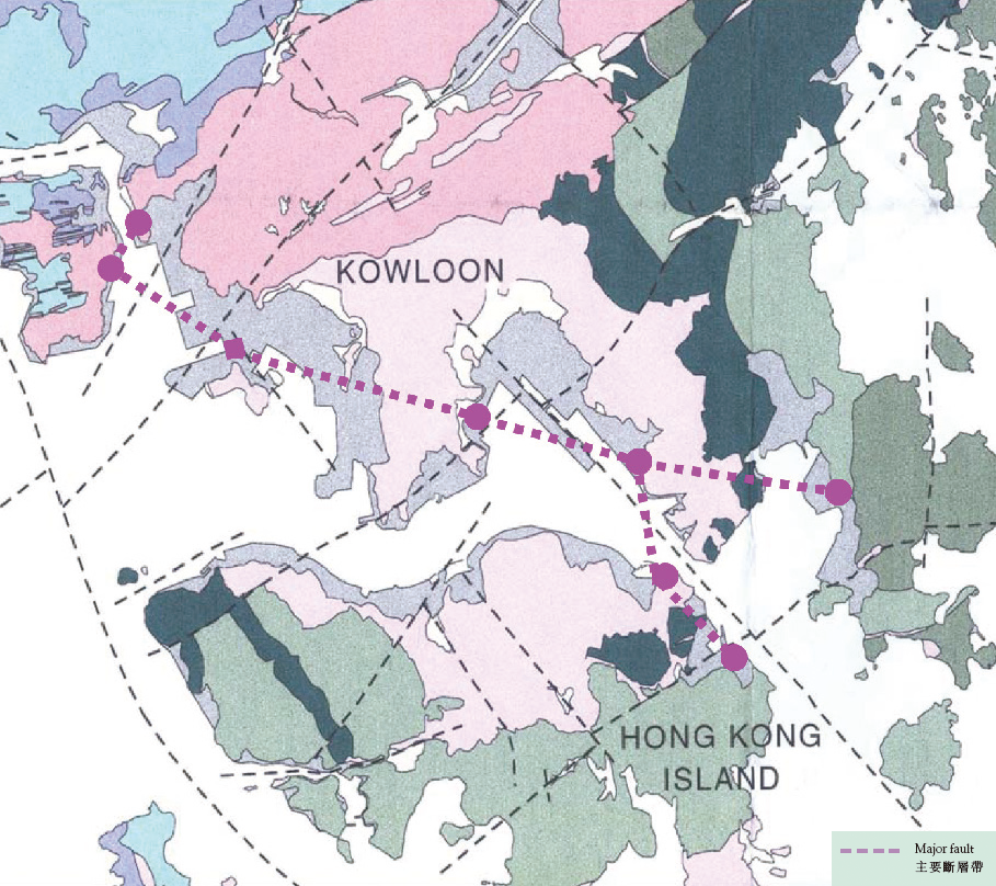
Geological map for HATS Stage 1 works
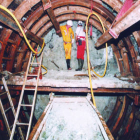
Manual excavation through Lead Mine Pass Fault in Tunnel F from Chainage 744 to Chainage 760
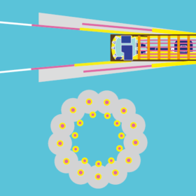
Pre-excavation grouting
Challenge 3: Ground Investigation to Reduce Tunnelling Risks
Solution: Comprehensive Ground Investigation Programme with State-of-the-art Technology
The importance of investigating the ground conditions beforehand to facilitate proper planning and design for the tunnelling works cannot be over-emphasised. The traditional ground investigation method involves drilling vertical and inclined boreholes. For Stage 1 tunnels, a total of 144 boreholes were drilled during the planning and design stage to investigate the ground conditions. This provided a general picture of the geology along the tunnel alignment, but not any direct information on the intermediate tunnel sections between the boreholes.
Learning from Stage 1, we specifically drilled a total of 150 boreholes for Stage 2A tunnel works to investigate the ground conditions more thoroughly. We also adopted a state-of-the-art technology called Horizontal Directional Coring (HDC) to take continuous core samples at strategic locations along the tunnel alignment.
This was how we applied HDC to Stage 2A. The drilling angle was around 45 degrees at entry. Once the drill had entered the bedrock, directional steering was applied in accordance with the planned trajectory, allowing for continuous coring at about eight metres above the designed crown level of the tunnels. Apart from avoiding disturbance to the actual alignment, this would enable us to obtain information close to the tunnel crown level for assessment of roof stability problems. The beauty of HDC was that it gave comprehensive information for the designer to mitigate the risks identified and the tenderers to price the job.
The longest continuous directional coring completed was 1,247 metres, a new record for Hong Kong. A total of about 5 kilometres of horizontal directional coring was completed successfully for Stage 2A. This comprehensive ground investigation programme using vertical and inclined boreholes, supplemented with information obtained from HDC, proved highly valuable in the subsequent design of ground support and groundwater ingress control, and in the assessment of settlement within the tunnel influence zone.
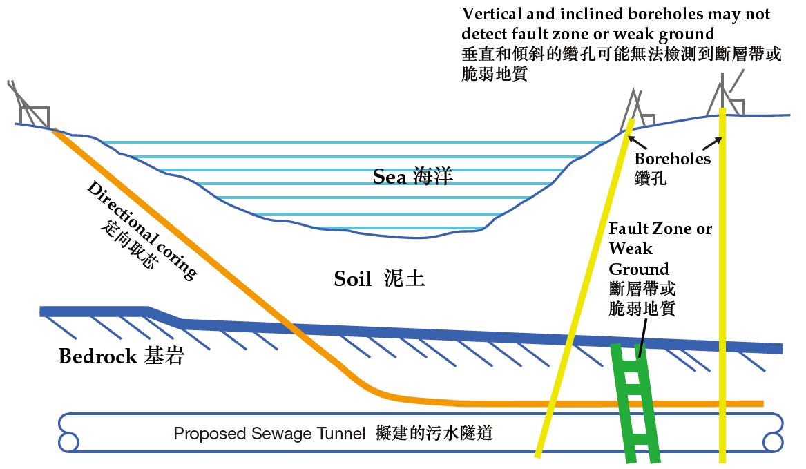
Directional Coring Trajectory
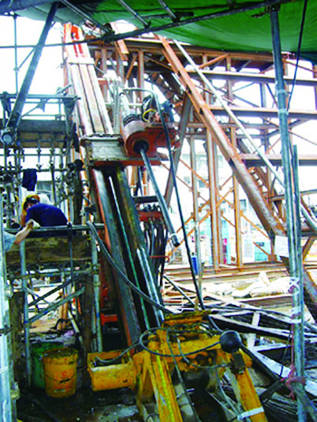
Setup for directional coring
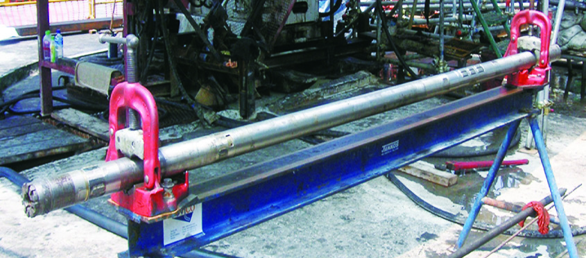
Directional barrel
Challenge 4: Constructing Small-Diameter Tunnels in Adverse Ground Conditions
Solution: Horizontal Directional Drilling
The construction of twin 600-millimetre diameter rising mains between the Ap Lei Chau and Aberdeen Preliminary Treatment Works (PTWs) in Stage 2A was a special case worth mentioning.
While the drill and blast method has many merits as discussed before, it is not ideal for constructing small-diameter tunnels. Typically, a horse-shoe section of about 3.5 meters wide and 4 metres high is required to provide working space for the blasting and pre-excavation grouting operation. After excavation, the section has to be reduced to the required size of the conduit by infilling the overbreak with concrete, which is neither economical nor environmentally friendly.
Furthermore, we were well aware of the presence of the Aberdeen Fault which crossed the alignment of the tunnel between the Ap Lei Chau and Aberdeen PTWs. The ground is highly variable and its effect on excavation could only be known when the weak zone is actually encountered during excavation. Given the uncertainty of ground conditions, and to minimise the safety risks of ground collapse during excavation to frontline workers, we decided to adopt Horizontal Directional Drilling (HDD) for completing this section of twin tunnels. The HDD technique means that a pilot hole of small size is drilled along the designed alignment, after which the pilot hole is progressively reamed by stages to the required larger size.
Even so, the HDD technique encountered additional difficulties. The twin tunnels are on a curved alignment both horizontally and vertically. The length of these tunnels, at about 1.4 kilometres, is also approaching the maximum limit of HDD drilling equipment. Moreover, pilot hole directional control proved difficult. This was because HDD directional control, which is guided by the magnetic field of the Earth, was interfered by the magnetic field produced by high voltage electric cables on the seabed nearby. The problem was finally resolved using a mobile magnetic source on a boat above the tunnel alignment.
Furthermore, the rock turned out to be much harder than expected during the reaming operation, which caused abnormal wear and tear to the drilling bits and breakage of the drilling rods. The team reinforced the drilling bits and closely monitored the drilling force to avoid overstressing the drilling rods during reaming. After much patient drilling, the team finally achieved breakthrough and high-density polyethylene pipes were pulled through the reamed holes. HDD had been successfully deployed to drill a unique section of the Stage 2A tunnel system.

Horizontal Directional Drilling Method
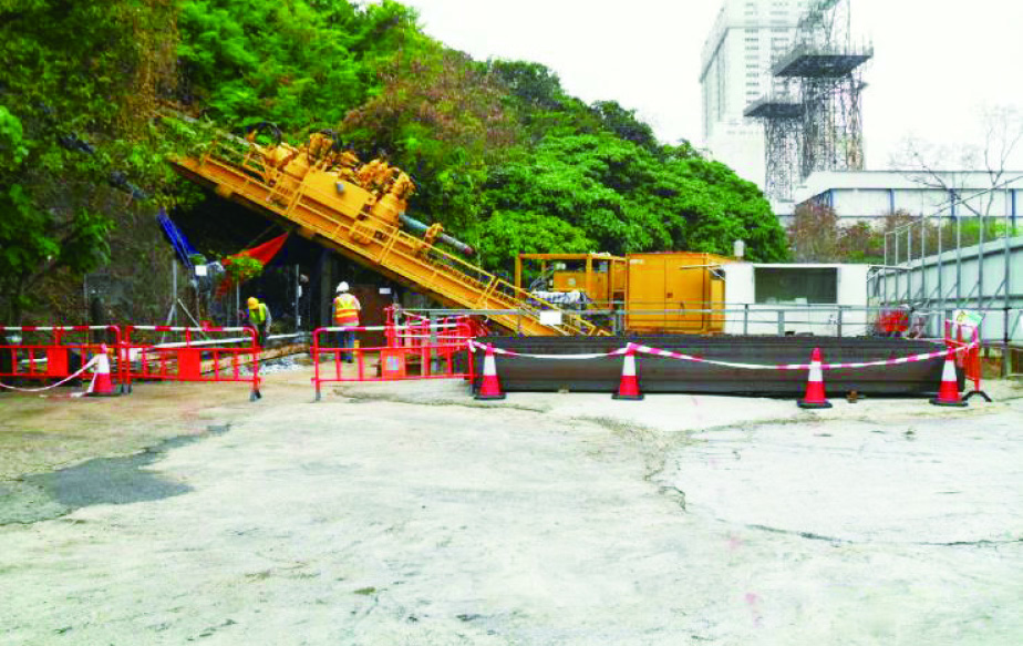
Setup of horizontal directional drilling
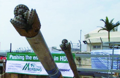
Completion of pilot hole drilling
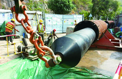
Completion of pipe pulling
Challenge 5: Launching TBM in Soft Ground
Solution: Artificial Ground Freezing
TBM was used in one instance in Stage 2A tunnel construction. An earth-pressure-balancing slurry-shield TBM was chosen to construct an interconnection tunnel in soft ground at about 30 metres below ground level between the Main Pumping Station 1 (MPS1) and Main Pumping Station 2 (MPS2) at Stonecutters Island Sewage Treatment Works (SCISTW). The tunnel would be 250 metres long with a diameter of 4 metres. The challenge was how to control the sudden inrush of soil and groundwater during the breakthrough operation of TBM at the launching shaft and the inlet chamber of MPS2, as well as to limit potential settlement of existing facilities in the close vicinity.
The project team decided to adopt Artificial Ground Freezing (AGF) technique as the mitigation measure. AGF quickly forms a frozen soil block, which stops water inflow and also acts as temporary support to facilitate the TBM breakthrough at the launching shaft and the inlet chamber. Two-dimensional thermal analysis was used to help determine the arrangement of the ground freezing pipes and to estimate the time and energy required to form the frozen soil wall at the right temperature.
Brine, or salt water solution, was used as the coolant for AGF. Using an industrial refrigeration system, brine was lowered to a temperature of –28°C to form a 2.5-metre thick frozen block with a temperature of –16°C in front of the TBM breakthrough, which blocked out groundwater and also acted as temporary support. Indeed, this was the first time in Hong Kong that brine was successfully used in AGF as an alternative coolant to liquid nitrogen which is commonly adopted, another innovation of the HATS project.
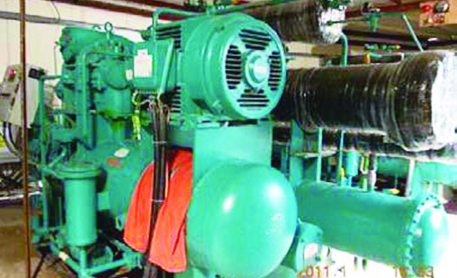
Refrigeration plant
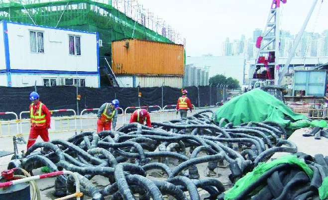
Insulated delivery and return pipes

Tunnel boring machine fabrication in Shanghai
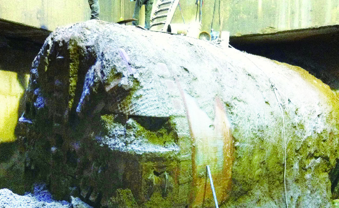
Breakthrough by tunnel boring machine “Victoria” at inlet chamber
Challenge 6: Deterioration of Concrete Quality During Long-Distance Pumping
Solution: Special Concrete Mix and Telescopic Formwork
The length of the sewage tunnel sections posed problems for concrete pumping, as concrete quality could deteriorate during the long pumping process. Long-distance concrete pumping was necessary to complete concrete lining works for the tunnels, sometimes at lengths of up to 3.5 kilometres. The excessive heat generated by the long pumping operation was highly detrimental to the quality of the concrete, not to mention segregation of the concrete when pumped over such a distance. As the lining works were a critical activity in the construction programme, an innovative solution was called for.
The project team began work on two fronts: find the right concrete and identify a device to place the concrete. Various special concrete mixes and designs were explored in order to develop a self-compacting concrete with sufficiently high workability and early strength development. The concrete temperature had to be carefully controlled too, such that heat generated during pumping would not lead to early setting and hardening of the concrete within the pumping pipes.
The project team also decided on a tailor-made telescopic formwork device, at a length of 120 metres, specially designed to facilitate continuous concrete placing. Both the special concrete mix and the formwork proved effective, which greatly expedited the lining works to meet the very tight construction programme.
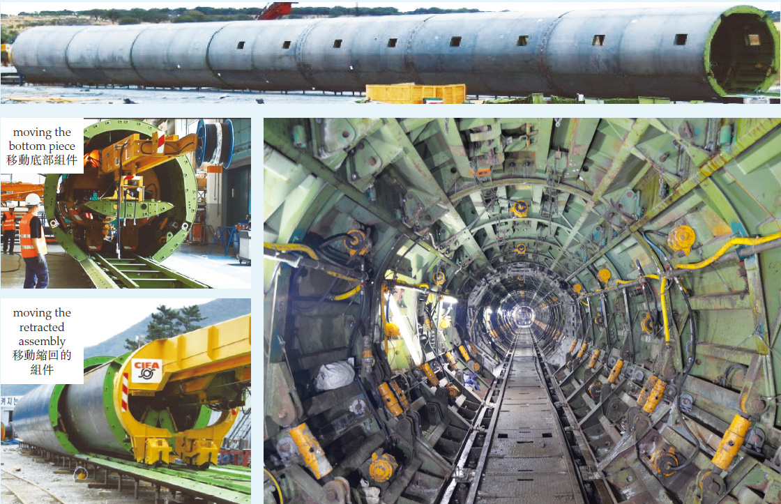
Telescopic lining formwork
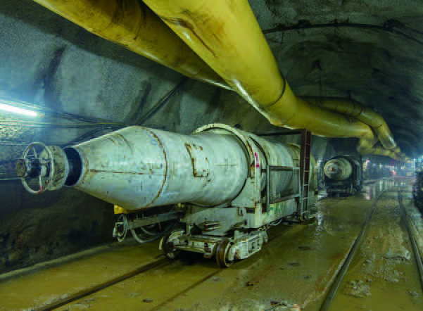
Concrete mixing equipment
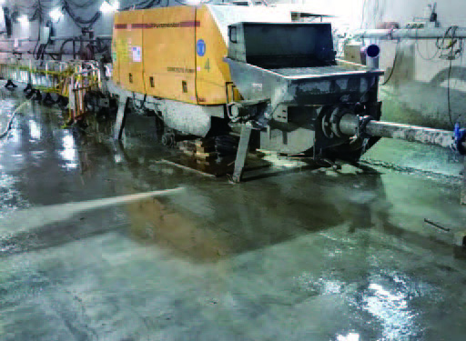
Concrete pumping equipment
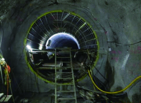
Concrete lining completed
Challenge 7: Crossing Major Traffic Routes and Important Infrastructures
Solution: Careful Control and Close Communication with Key Stakeholders
Some tunnel sections in both Stages 1 and 2A are located underneath existing major transport tunnel routes such as the Eastern Harbour Crossing (EHC) and the MTR Tsuen Wan Line and Airport Express. These tunnel sections also run below important infrastructures of the city such as the Kwai Chung container terminals. It was therefore necessary to tunnel underneath these major infrastructures while keeping settlement and vibration to a negligible level to avoid disrupting the normal operation and services of these infrastructures. This posed another major challenge to the HATS project.
Our starting point was careful application of the appropriate construction technique as mentioned earlier, and close monitoring. No less important was close communication with both the operators of these infrastructures and related government departments to alleviate their concerns before and during tunnelling. Comprehensive monitoring devices and instruments were also installed on an extensive scale to closely monitor the effects of the tunnelling works on these infrastructures.
Through effective communication and close liaison, the project team built trust and good working relationships with all relevant stakeholders including the MTRC as well as operators of EHC and the container terminals. All tunnelling works under HATS Stages 1 and 2A were safely completed without affecting the major infrastructures in any material way. For HATS Stage 2A, we went a step further by realigning, in an early stage, the initially planned route of the cross harbour section of our tunnel to avoid crossing underneath the Western Harbour Crossing, another major infrastructure.
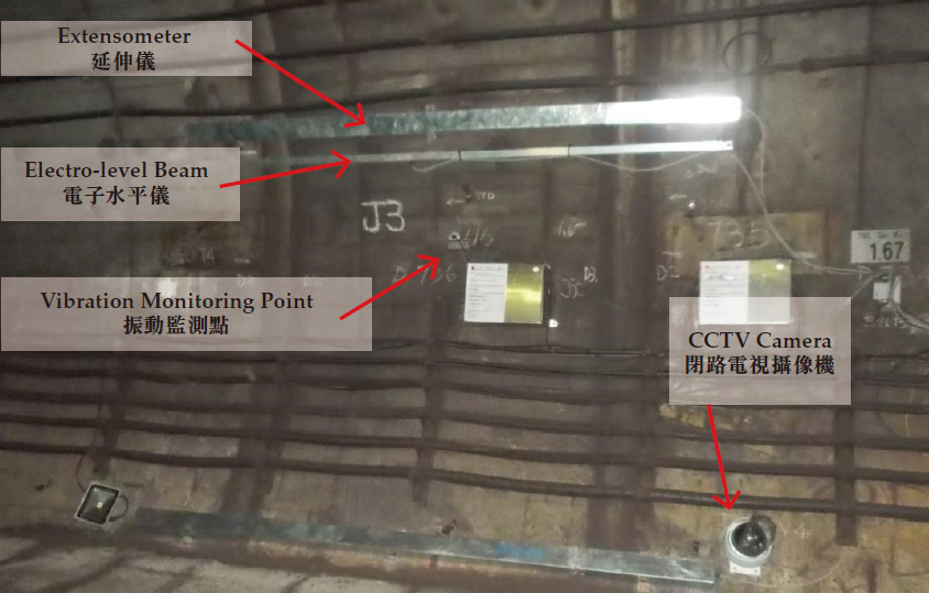
Devices installed in MTR tunnels for monitoring the blasting underneath
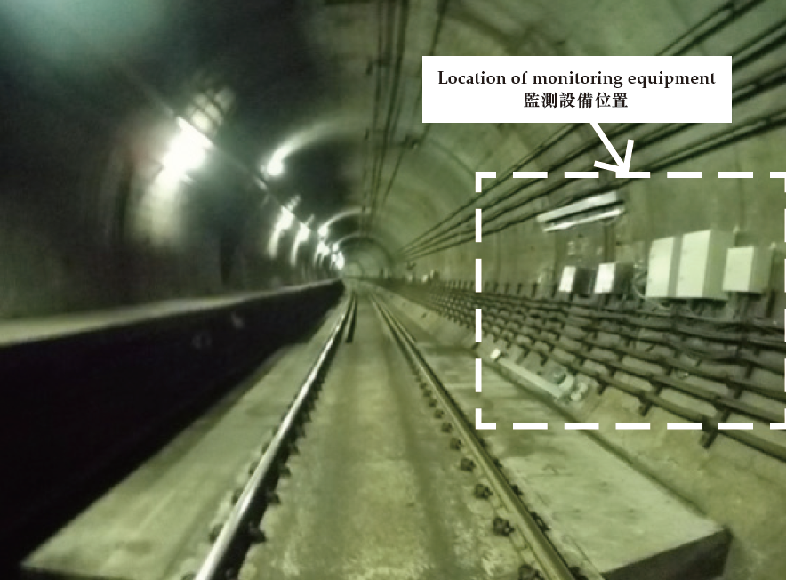
MTR tunnels monitoring equipment
POSTSCRIPT
“We must never forget the human dimension in any engineering project. For a few years our team communicated closely with stakeholders along the HATS tunnel alignment, such as elderly homes and schools. We took all necessary steps to make sure that the noise and disturbance caused by tunnelling works to the neighbourhood was kept to a minimum. Through drawing competitions, young people had the opportunity to express and paint their vision of a clean harbour.”
“A memorable experience was using Horizontal Directional Drilling for constructing the Ap Lei Chau to Aberdeen tunnel, a fairly new technique for Hong Kong at that time and very challenging. Looking back, HATS taught us that every innovative idea must come with careful risk management for it to work. Mutual trust and team spirit among the Drainage Services Department, consultants and contractors are also vital for HATS to succeed.”
Keith TSANG
Director, AECOM

