Dear Harbour,
To reduce pollution in Your waters, our first crucial task in the 1990s was to construct a deep tunnel system for Stage 1 of HATS.
Comprising 23.6 kilometres of deep hard-rock tunnels at depths of up to 150 metres, this labyrinth of tunnels is truly one of Hong Kong’s engineering wonders. The tunnels were designed to collect preliminarily treated sewage from the whole urban area of Kowloon, from Tseung Kwan O in the east to Tsuen Wan in the west, as well as from Chai Wan and Shau Kei Wan on Hong Kong Island, and convey it to the Stonecutters Island Sewage Treatment Works (SCISTW) for centralised chemically enhanced primary treatment. The effluent would then be discharged via a 1.7-kilometre outfall off SCISTW to the western approach of Victoria Harbour.
Stage 1 also included upgrading works at the seven existing Preliminary Treatment Works (PTWs) at Kwai Chung, Tsing Yi, Kwun Tong, To Kwa Wan, Tseung Kwan O, Chai Wan, and Shau Kei Wan, all located at connecting points of the deep tunnel system.
Upgrading Seven PTWs
Seven existing PTWs of Stage 1 served to protect the deep tunnel system against the risk of sediment accumulation and blockage of tunnel. Works included the installation of 6-millimetre fine screens to trap small objects and degritting facilities to remove 95% of grit greater than 0.2 millimetres.
Air extraction system complete with modular activated carbon type deodourisation units were added to minimise odour nuisance to the neighbourhood. The operational control system was also upgraded.
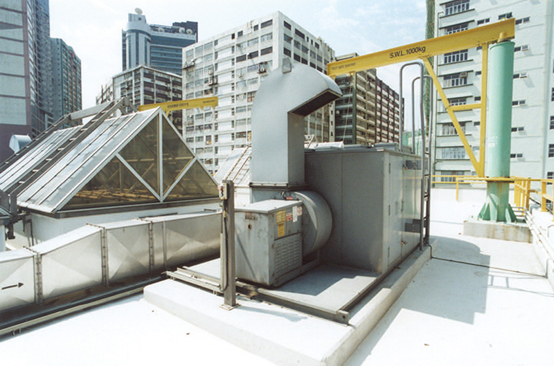
Air extraction system complete with modular activated carbon type deodourisation units on the roof top of Chai Wan PTW
Choice and Design of Deep Tunnel System
Sewerage networks are typically constructed by the open trench method, following the alignment of the road system. However, given Hong Kong’s unique urban environment, the open trench method would cause major traffic disruptions, clashes with existing utilities, environmental nuisance, loss of business to shops and other social disruption.
An innovative approach using a deep tunnel system was therefore selected to eliminate these issues and disruptions to the public.
During the early stage of development in Hong Kong, all sewage flows generated in urban areas were essentially conveyed to PTWs for simple screening and grit removal before discharge to the Harbour. It was therefore feasible to design a tunnel system linking the seven existing PTWs under Stage 1 to convey the sewage collected to the SCISTW. Straight alignments were adopted between the PTWs to minimize the length of the tunnels. After studying the geological information, the project team decided to locate the tunnels in the bedrock stratum at depths of about 80 metres to 150 metres below sea level in order to maintain a minimum rock cover of 30 metres.
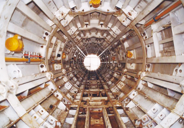
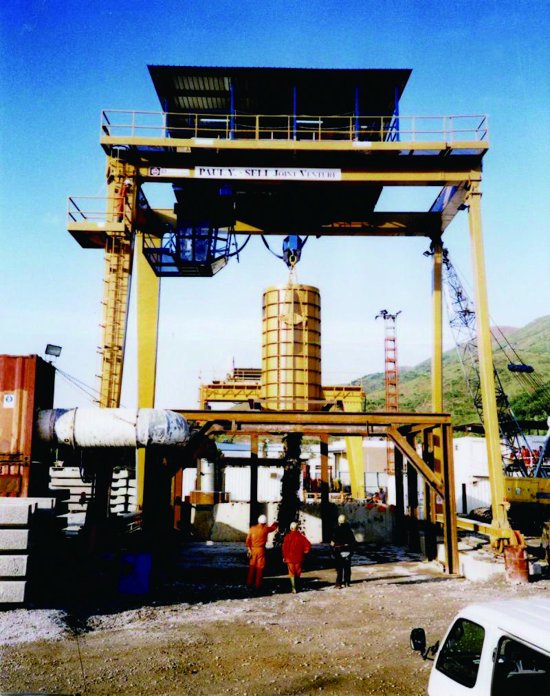
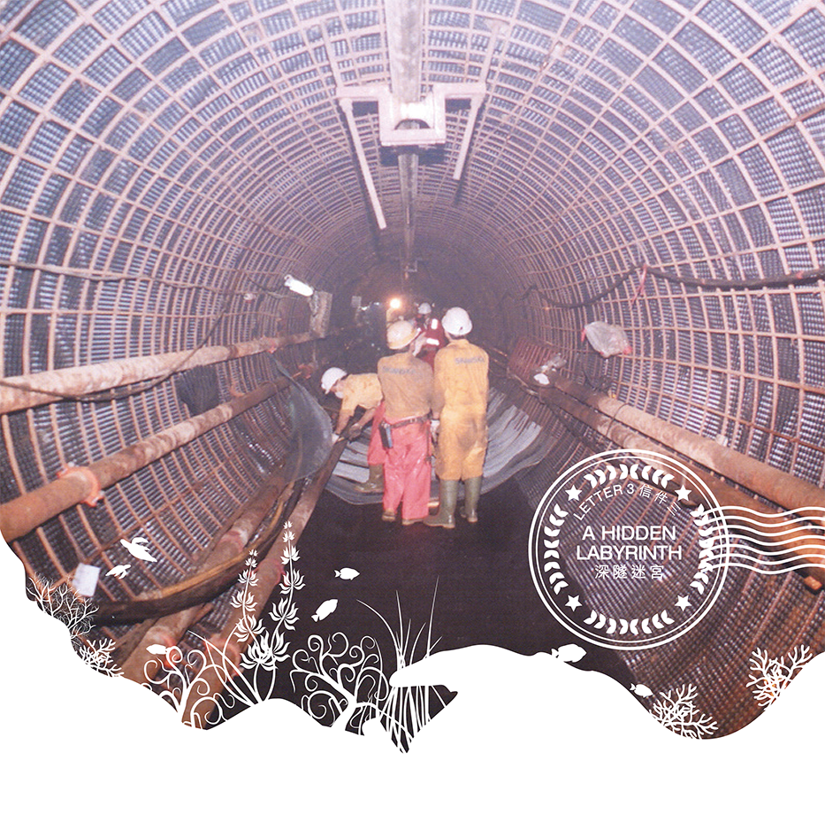
Tunnel formwork in Tunnel F from Tsing Yi to Stonecutters Island
Placing the tunnels in rocks at these great depths would minimise any interference with the use and development of the land above. In order to do away with the need for resumption of private lots located along the tunnel alignment, the Sewage Tunnels (Statutory Easements) Ordinance (Cap. 438) was enacted in 1993 to empower the Government to create legal rights to construct, maintain, and operate the tunnels by following appropriate statutory procedures. It also provided a mechanism for the relevant land owners to raise objections and seek compensation if their private rights were affected.
The tunnel system was designed to operate as an inverted siphon, which would save substantial pumping energy compared to a gravity feed system. As future maintenance of the tunnels would be difficult, the designed flow would achieve self-cleansing velocity during the peak flow periods daily, so as to scour any solids or silts settled during other periods.
The great depth of the tunnel system means that any pockets of gas in the system might form air locks at the drop shafts thus obstructing the inflow of sewage. To minimise air entrainment, a specially designed vortex inlet was adopted with deaeration chambers at the bottom of every shaft. The tunnels are also designed to slope upwards at a minimum gradient of 1 in 500 to prevent the accumulation of residual air.
How Inverted Siphon Works

Geology and Tunnel Excavation
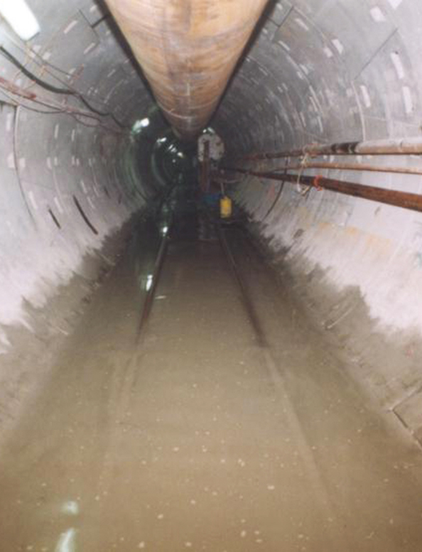
Geological conditions in Hong Kong made the construction of the HATS deep tunnel system especially challenging. Overall, the Stage 1 tunnel excavation works took place mainly in unweathered hard rock which inherently contained interconnected fissures in the form of rock joints and fractures. At such great depths below sea level, significant amount of salty ground water under high pressure would flow into the tunnels through the rock fissures.
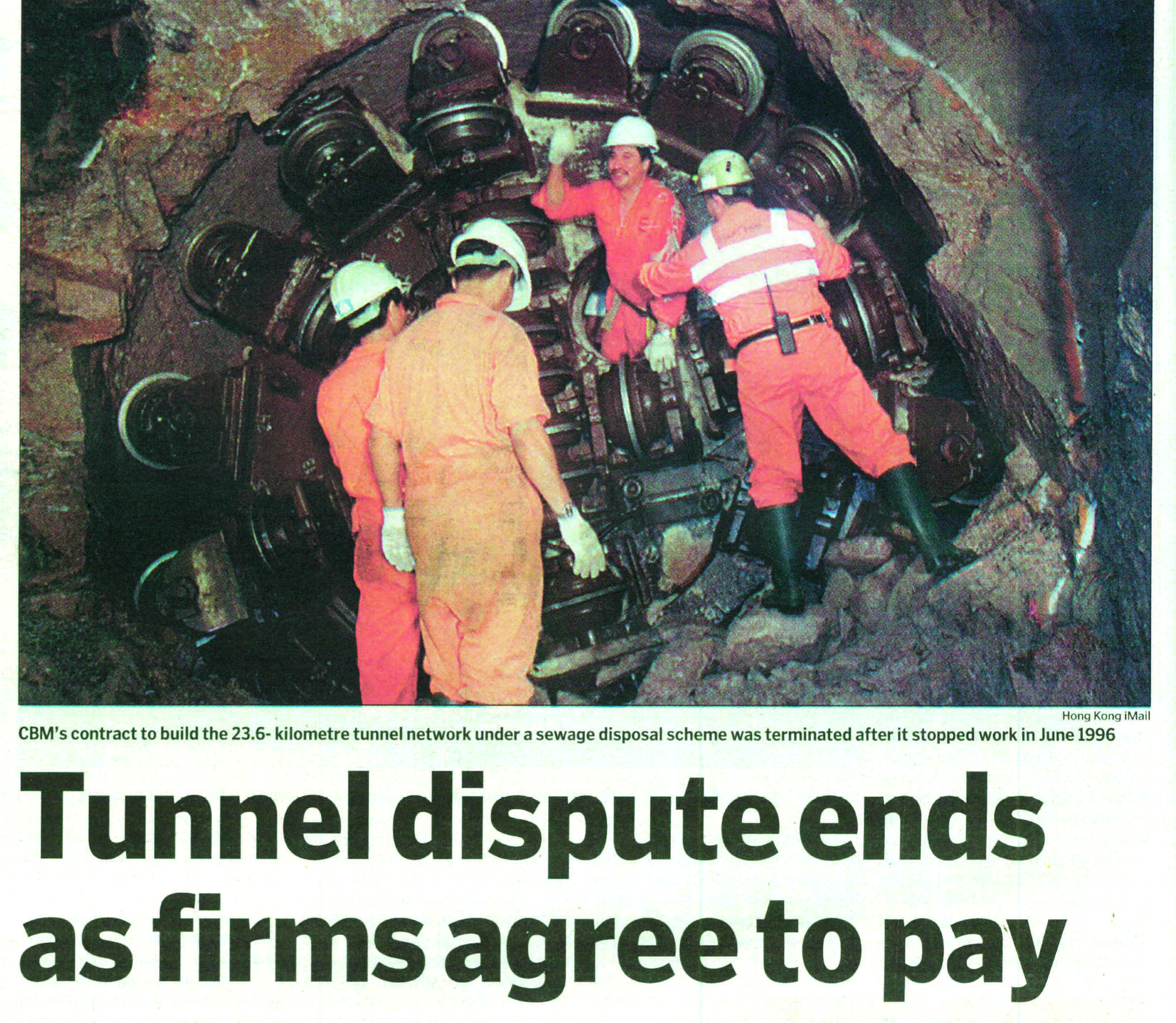
Hong Kong iMail of 2 October 2001
Such inflow, if not properly controlled, would draw down the ground water table and cause ground settlement. Depending on the quantity of inflow, water ingress would also cause practical difficulties to tunnel excavation such as rusting of construction equipment and flooding. Isolated sections of weak ground in highly weathered rock dykes and faults would also create great difficulties for tunnelling, particularly in the presence of high water ingress under great pressure.
Difficulties in Tunnelling
The Stage 1 tunnels, with lengths ranging from 3.6 to 5.5 kilometres, were excavated using five Tunnel Boring Machines (TBMs). The only exception was the shortest tunnel, at 0.78 kilometre in length, between Kwai Chung and Tsing Yi where the conventional drill and blast method was used.
At the time of their construction, the HATS Stage 1 tunnels were the deepest tunnels ever constructed in the world and there was hardly any experience from similar works for reference. This posed a major challenge to the tunnelling works which had to be carried out under the difficult geological conditions mentioned above.
The contractor for Stage 1 tunnels commenced works in early 1995. Water ingress under high pressure and the presence of weak ground at isolated locations soon created difficulties in tunnelling works. The project team tried its very best to work out feasible solutions together with the contractor to allow the works to proceed. However, the contractor eventually considered that it was “physically impossible” to complete the tunnelling works and gave up any further attempt to continue with the works.
Tasked with the mission to restore Your health, dear Harbour, we did not give up despite the serious difficulties encountered. We promptly took over all works from the contractor in December 1996 and relentlessly arranged for recommencement of the tunnelling works. As You will see later in this letter, it was subsequently demonstrated that the tunnelling works, though difficult, were viable. The contentions raised by the contractor were untenable and it turned out that it had to pay significant financial compensation to the Government for its unilateral decision to relinquish the tunnelling works.
Tunnelling Continued
Starting from July 1997, three new contractors were appointed to recommence the tunnelling works. Despite the serious technical difficulties, we continued the tunnelling works with unyielding and persistent efforts and actively worked out solutions to tackle the complications. We believed that grouting the ground ahead of tunnel excavation to seal rock fissures by pre-excavation grouting was the most appropriate way forward in reducing ground water ingress under high ground water pressure.
What followed was the difficult but successful task to modify all the existing five TBMs used for Stage 1 tunnelling works to provide them with mechanical equipment for drilling grout holes around the tunnel perimeter in front of the excavation face. In addition to pre-excavation grouting, installation of ground supports in the forms of timber laggings, reinforcement, steel support frames and concrete lining were also adopted for maintaining stability during excavation through weak ground.
The project team also decided that it was necessary to set a limiting figure on the amount of ground water to be allowed to enter the tunnel during excavation, but this posed another major challenge. On the one hand, allowing too much water to enter the tunnel would increase construction difficulties and cause ground water table drawdown that might lead to ground settlement. On the other hand, it would be very difficult to achieve an overly stringent allowable water ingress limit even with the use of pre-excavation grouting.
To tackle this, different allowable water ingress limits were worked out for different areas and a balance was carefully maintained through an observational approach to allow tunnel excavation to proceed in a carefully controlled and orderly manner. With determination and perseverance, the project team achieved a major milestone in November 2000 with the break-through of the last tunnel section from To Kwa Wan to Stonecutters Island. While settlement had occurred in some locations which required patching up to restore serviceability of the settled ground, there was no impact to public safety in any material way.
The many setbacks during the tunnelling process marked the most challenging aspect of Stage 1 works, not to mention community concerns and queries about HATS triggered by these issues. By 2001, all Stage 1 works including the deep tunnel system were completed. Once operational, the deep tunnel system began collecting over 1.3 million cubic metres of preliminarily treated sewage every day from the seven PTWs in Kowloon and north-eastern Hong Kong Island for chemically enhanced primary treatment at SCISTW and discharged through the outfall off Stonecutters Island. The deep tunnel system laid a solid foundation for the successful commissioning of the entire HATS Stage 1 in December 2001.
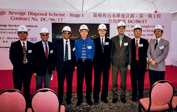
Breakthrough ceremony of Tunnel C Tseung Kwan O to Kwun Tong was held on 9 November 1999
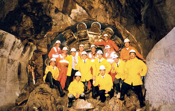
Celebrating the tunnel breakthrough on site
HATS Stage 1 Tunnels Alignment
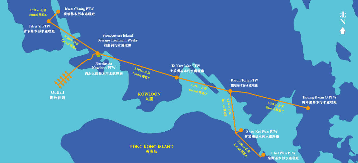
HATS Stage 1 Tunnels Longitudinal Profile

Information of HATS Stage 1 Tunnels

Notes:
1. Tunnel A and Tunnel B were excavated using the same tunnel boring machine (TBM).
2. “D&B” means drill and blast method.
3. “PC Segment” means precast concrete segment.
Vortex Inlet of Typical Drop Shaft
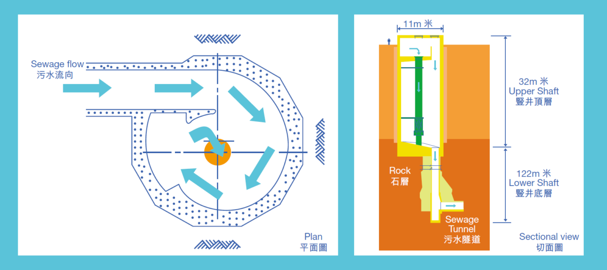
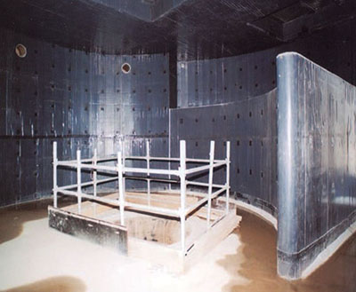
Vortex chamber
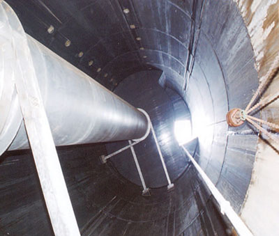
Interior of upper drop shaft
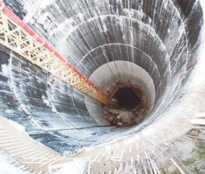
Chai Wan drop shaft under construction
POSTSCRIPT
“I was involved in HATS from 1993 to 2009 and went through the most challenging days in Stage 1 works — such as our re-entering the work sites, conducting arbitration with the contractor who abandoned the works, resolving the problem of serious underground water ingress into the deep tunnels as well as settlement issues in certain areas along the tunnel alignment. However, it is also because of these precious lessons learnt from Stage 1 that we were able to grasp the techniques of deep tunnel construction for Stage 2A and became a world-class pioneer in this respect.”
“HATS is a mega project involving many profound issues and must be handled with great care. We had to control the cost and programme and strike a balance in every respect. We have weathered the most stormy days and gathered valuable experiences, which will make the team more confident in dealing with future challenges.”
Raymond TAI Wai-man
Former Chief Engineer/Project Management, DSD

